232/2 · PHYSICS (Theory) · Paper 2 · Nov. 2025 · 2 hours
Instructions: This paper consists of two sections, A and B. Answer all the questions in sections A and B. All working must be clearly shown. Non-programmable silent electronic calculators may be used.
Section A (25 marks)
1. Figure 1 shows a ray of light incident on a plane mirror at an angle of 40°. A second plane mirror is placed at an angle of 70° to the first mirror.
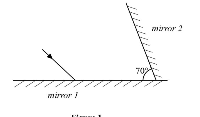
Draw the path of the ray to show how it is reflected from the second mirror. Include all the necessary details. (2 marks)
2. State what happens when a positively charged rod is placed in contact with an uncharged rod. (1 mark)
3. Explain why lightning arrestors are made of thick copper wire. (2 marks)
4. Figure 2 shows a circuit diagram consisting of a bulb, three voltmeters, cells and a switch, connected by a student in the laboratory.
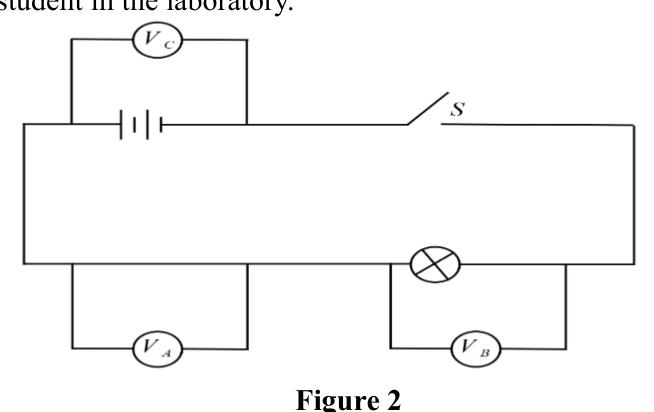
State, with a reason, the voltmeter that will show the highest reading when the switch is closed. (2 marks)
5. Figure 3 shows a pattern observed by students when studying the properties of magnets.
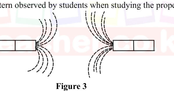
State the law of magnetism that is illustrated in Figure 3. (1 mark)
6. Figure 4 shows two parallel rays incident on a concave mirror from a distant object.
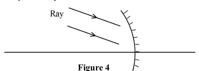
Complete the diagram to show the position of the image formed. (3 marks)
7. A student wants to construct a simple electromagnet. Apart from an iron nail, state one other main material the student requires. (1 mark)
8. Explain the function of the mixture of powdered carbon and manganese(IV) oxide in a dry Leclanché cell. (2 marks)
9. Describe how a ripple tank may be used to determine the wavelength of transverse waves. (3 marks)
10. A student observed that sounds from distant sources travel faster on warm nights than on cold nights. Explain this observation. (2 marks)
11. The refractive index of perspex is approximately while that of water is . Determine the refractive index of water with respect to perspex. (2 marks)
12. Explain how a diode is used in a rectification circuit. (2 marks)
13. State one application of total internal reflection. (1 mark)
14. State one device that may be used to detect infrared radiation. (1 mark)
Section B (55 marks)
15. (a) Describe how a magnet can be demagnetised by the hammering method. (3 marks)
(b) Figure 5 shows a wire moving out of a magnetic field. The wire is connected to a centre-zero galvanometer.
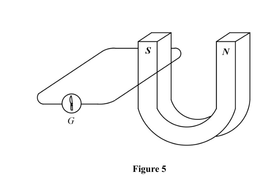
(i) Describe what is observed on the galvanometer as the wire moves out of the magnetic field. (2 marks)
(ii) Explain the reason for the observation described in (b)(i). (2 marks)
(iii) Explain how an increased speed of motion of the wire will affect the observation made in (b)(i). (2 marks)
(c) Explain how hysteresis losses can be minimised in a transformer. (2 marks)
16. (a) Students visited a power generation and transmission station. State the reason for each of the following observations that they made: (i) the voltage is stepped down; (1 mark) (ii) the transmission cables used are thick. (1 mark)
(b) State two risks that may arise from transmitting electricity at high voltage. (2 marks)
(c) A school uses electricity for lighting the classrooms. State two ways in which the electrical energy consumed in the classrooms may be minimised without reducing the number of bulbs. (2 marks)
(d) Kairu lit up a hall using 10 bulbs each rated 60 W, 240 V. Determine the: (i) current drawn by each bulb; (3 marks) (ii) energy consumed if the bulbs were used for 10 hours. (3 marks)
17. (a) Figure 6 shows a cathode ray oscilloscope in which a beam of electrons is cast on the screen to produce a spot.
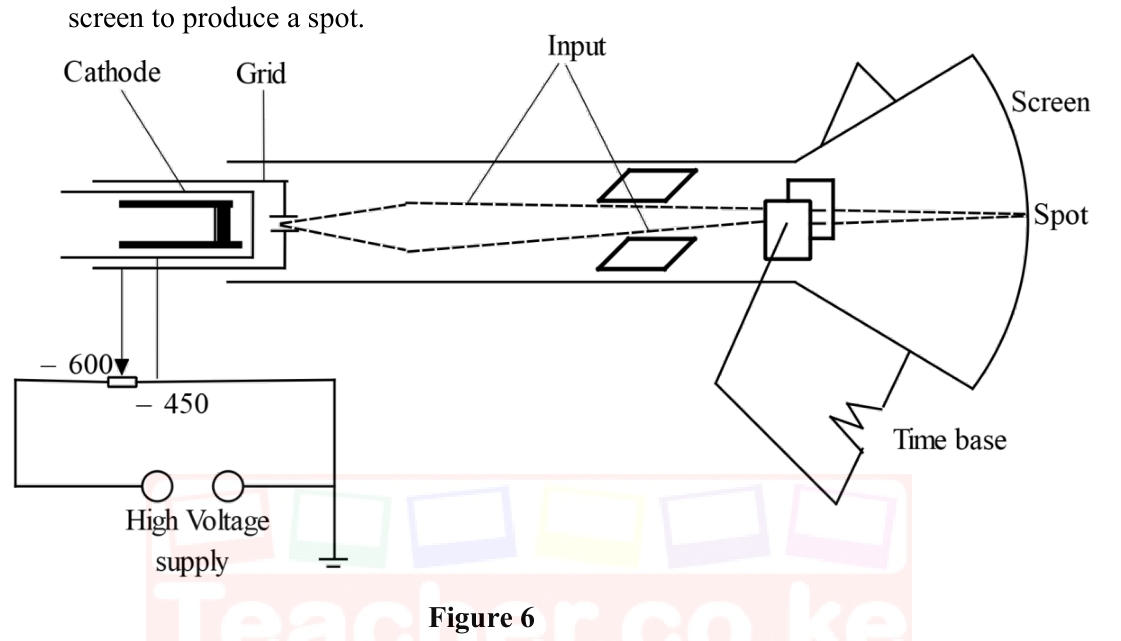
(i) Explain how the intensity of the spot is increased. (2 marks)
(ii) Explain what is observed on the screen when the time base is switched on, then switched off. (3 marks)
(b) State two uses of a cathode ray oscilloscope in a laboratory. (2 marks)
(c) A signal of wavelength 2.0 cm is input into a cathode ray oscilloscope. Given that the speed of the generated wave is m s⁻¹, determine its frequency. (2 marks)
18. (a) You are provided with a metre rule, a convex lens, a lens holder and a screen. With the aid of a diagram, describe how the focal length of the lens can be estimated. (4 marks)
(b) Figure 7 shows a graph of conductivity against temperature for a semiconductor.
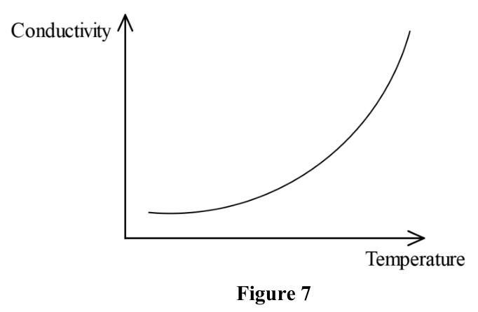
(i) On the same axes, sketch the conductivity–temperature relationship for a conductor. (1 mark) (ii) Explain the shape of the curve sketched in (b)(i). (2 marks)
(c) Figure 8 shows a circuit diagram in which a diode and a bulb are connected to an alternating current power source.
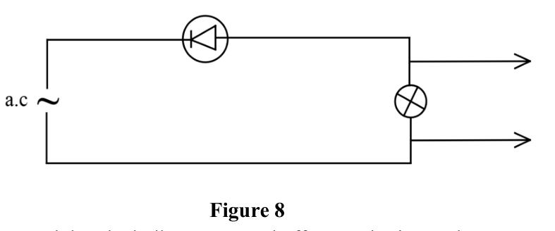
It is observed that the bulb goes on and off at regular intervals. (i) Explain the observation. (3 marks) (ii) Sketch the graph of voltage against time for the set-up. (2 marks)
19. (a) State the meaning of the term photoelectric effect. (1 mark)
(b) A student is provided with a UV radiation source and a zinc plate to demonstrate the photoelectric effect. (i) Identify the missing component. (1 mark) (ii) Using the apparatus provided and the component identified in (b)(i), describe how the photoelectric effect will be demonstrated. (3 marks)
(c) The work function of a certain metal surface is 4.8 eV. Radiation of wavelength m is directed onto the metal surface. Determine: (i) the work function of the metal in joules; (1 mark) (ii) the energy of the radiation; (3 marks) (iii) whether the radiation ejects photoelectrons from the metal surface. Give a reason. (2 marks) ( J s, m/s, J)