232/2 · PHYSICS (Theory) · Paper 2 · Dec. 2022 · 2 hours
Instructions: This paper consists of two sections, A and B. Answer all the questions in sections A and B. All working must be clearly shown. Non-programmable silent electronic calculators may be used.
Section A (25 marks)
1. Figure 1 shows three cardboards A, B and C with holes placed between a source of light and an observer.
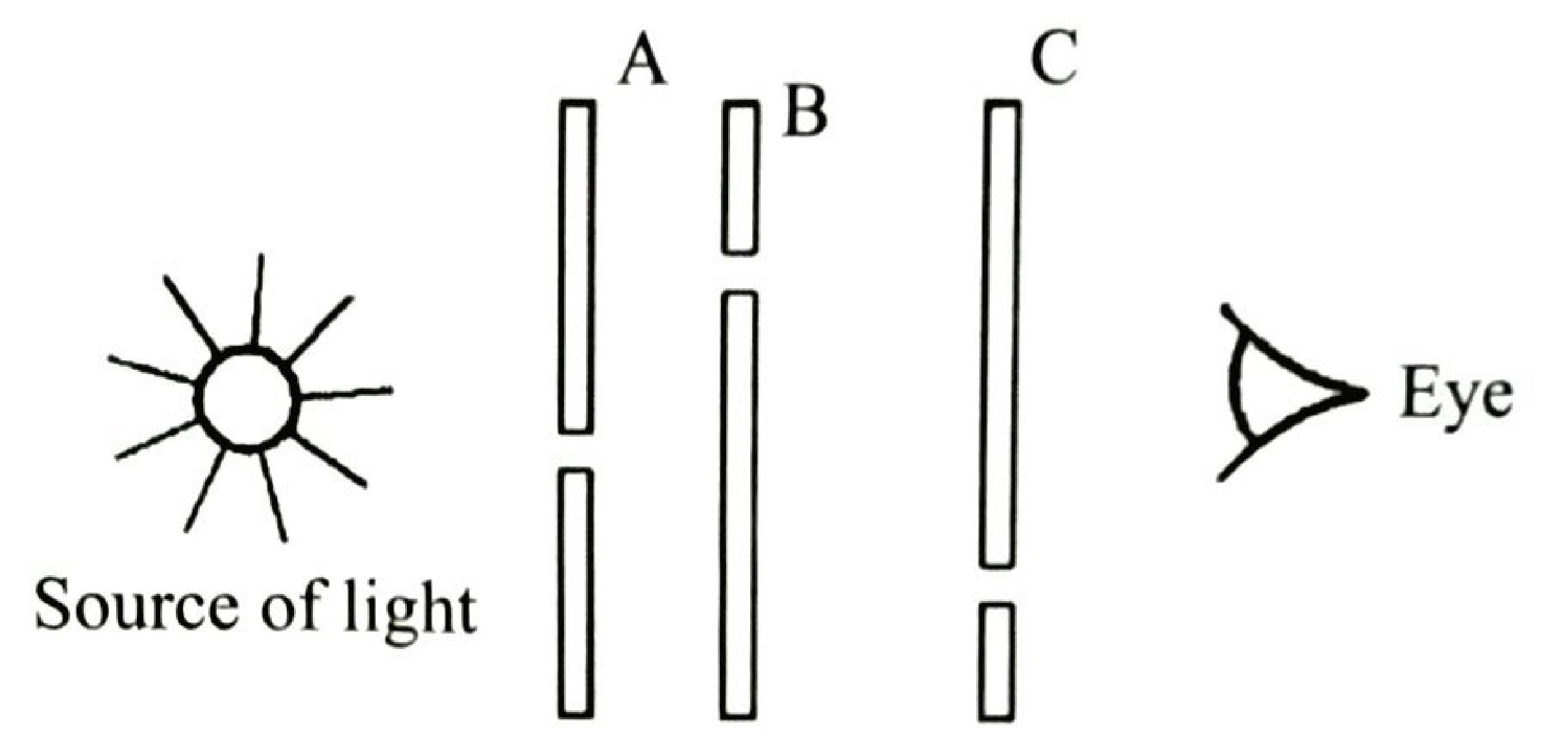
Explain what is observed. (2 marks)
2. State how a polythene rod acquires a negative charge when it is rubbed with a piece of cloth. (1 mark)
3. State one device that can be used to detect microwaves. (1 mark)
4. Figure 2 shows an incomplete circuit.
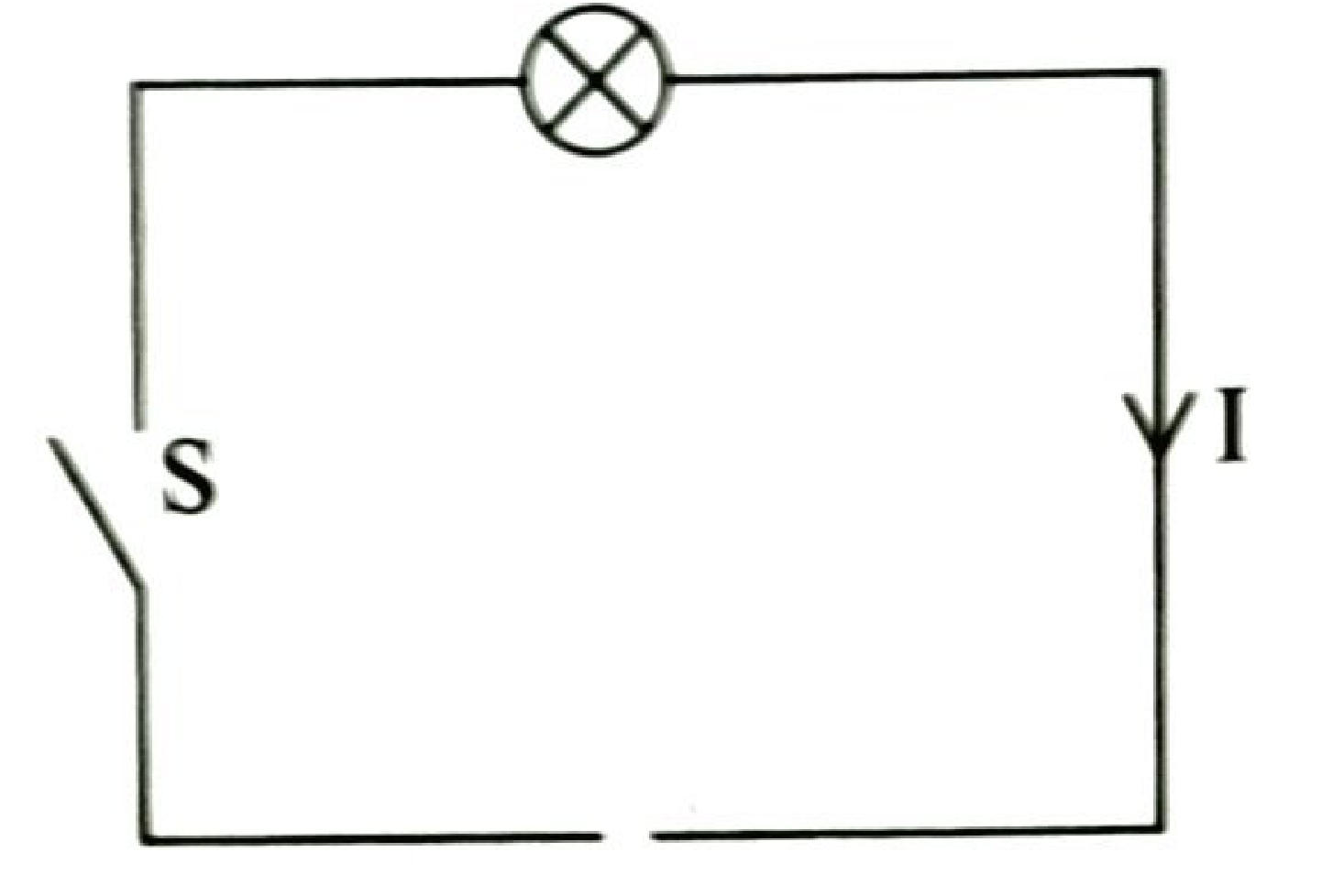
Complete the circuit by inserting a cell so that the current I flows in the direction shown when switch S is closed. (1 mark)
5. State the basic law of magnetism. (1 mark)
6. Figure 3 shows a vertical object O placed in front of a concave mirror whose principal focus is at F.
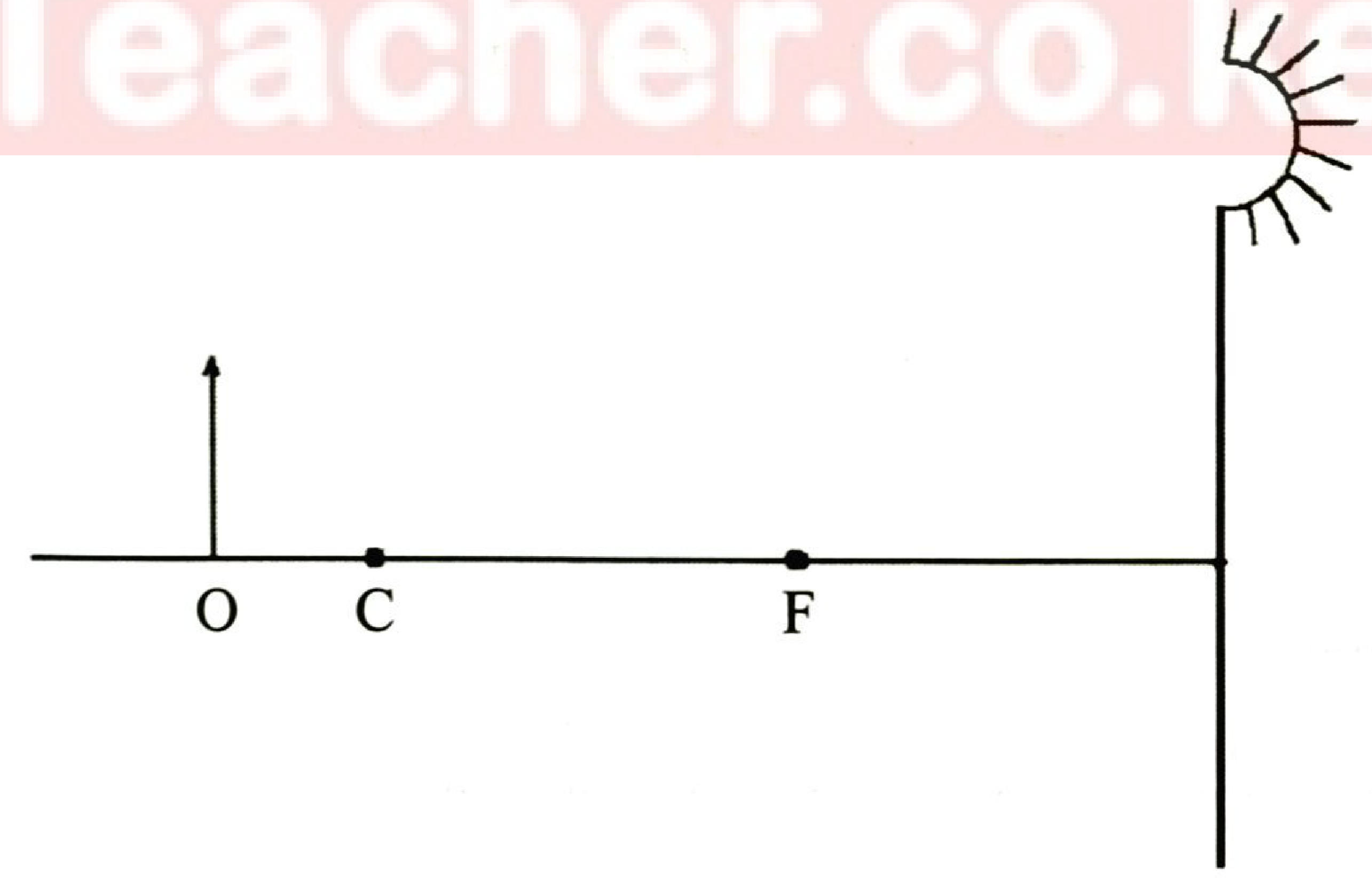
Draw a ray diagram to show how the image is formed. (3 marks)
7. State two properties of soft iron that make it suitable for use as the core of the electromagnet of an electric bell. (2 marks)
8. (a) State one reason why sound travels faster at sea level than in high mountains. (1 mark)
(b) State one condition necessary for two progressive waves to form a standing wave. (1 mark)
9. Two students stand 300 m from a wall. One bangs two pieces of wood together and at the same time the other starts a stop watch. They hear an echo after 1.8 seconds. Determine the speed of sound in air. (3 marks)
10. During an experiment to investigate the relationship between the angle of incidence and the angle of refraction for a ray of light travelling from air to glass, the values of and were determined.
(a) Sketch the graph of (y-axis) against for the values that were obtained. (1 mark)
(b) State how the refractive index of the glass can be obtained from the graph. (1 mark)
11. Figure 4 shows a circuit consisting of two resistors of 4 Ω and 8 Ω, a cell and voltmeters V₁ and V₂.
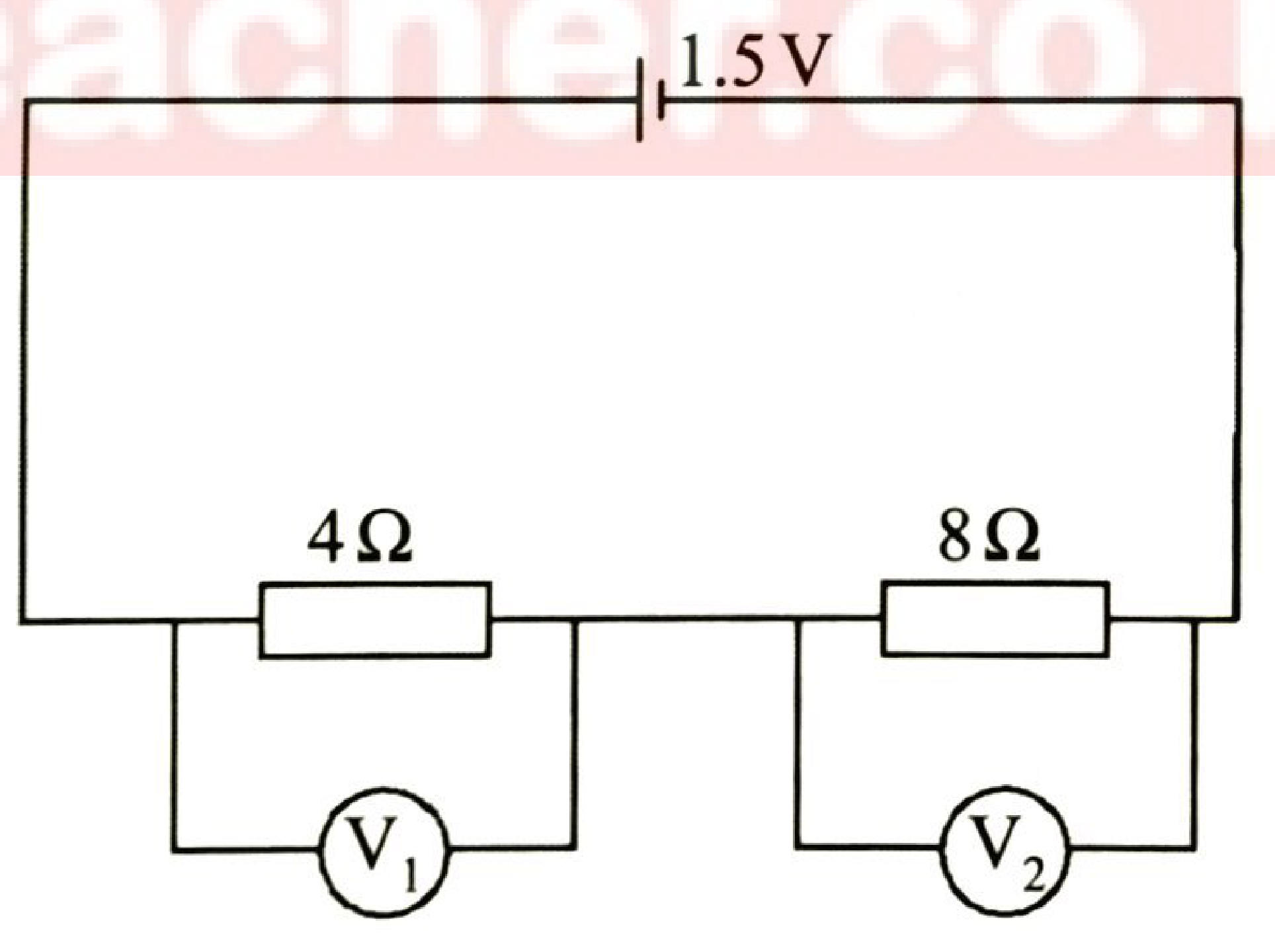
It is observed that voltmeter V₂ shows a higher reading than V₁. Explain this observation. (2 marks)
12. A heating element is rated 3 kW, 240 V. Determine the resistance of the element. (3 marks)
13. State two characteristics of images formed by diverging lenses. (2 marks)
Section B (55 marks)
14. (a) State Lenz's law of electromagnetic induction. (1 mark)
(b) Figure 5 shows a magnet held near a stationary solenoid.
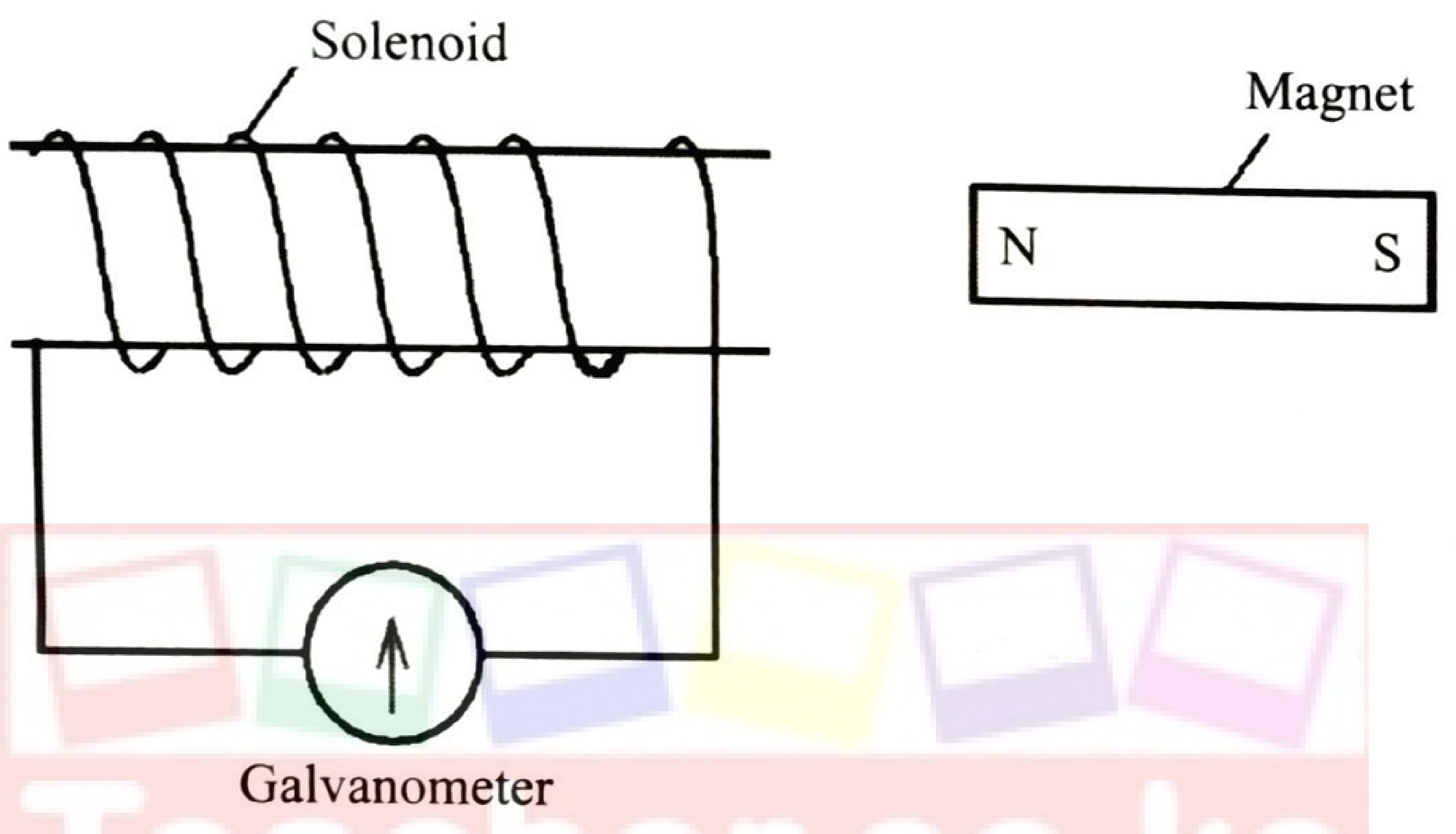
State what will be observed on the galvanometer when the: (i) north pole end is pushed into the solenoid; (1 mark) (ii) magnet is held stationary inside the solenoid; (1 mark) (iii) north pole end is pulled out of the solenoid. (1 mark)
(c) Explain what would be observed if the north pole of the magnet is now moved into the solenoid at a higher speed. (3 marks)
(d) State two causes of energy losses in a transformer. (2 marks)
15. (a) State the function of the ring main circuit in a domestic wiring system. (1 mark)
(b) Figure 6 shows a circuit consisting of switches S₁, S₂, S₃ and three identical lamps L₁, L₂ and L₃ connected to the mains supply through a fuse.
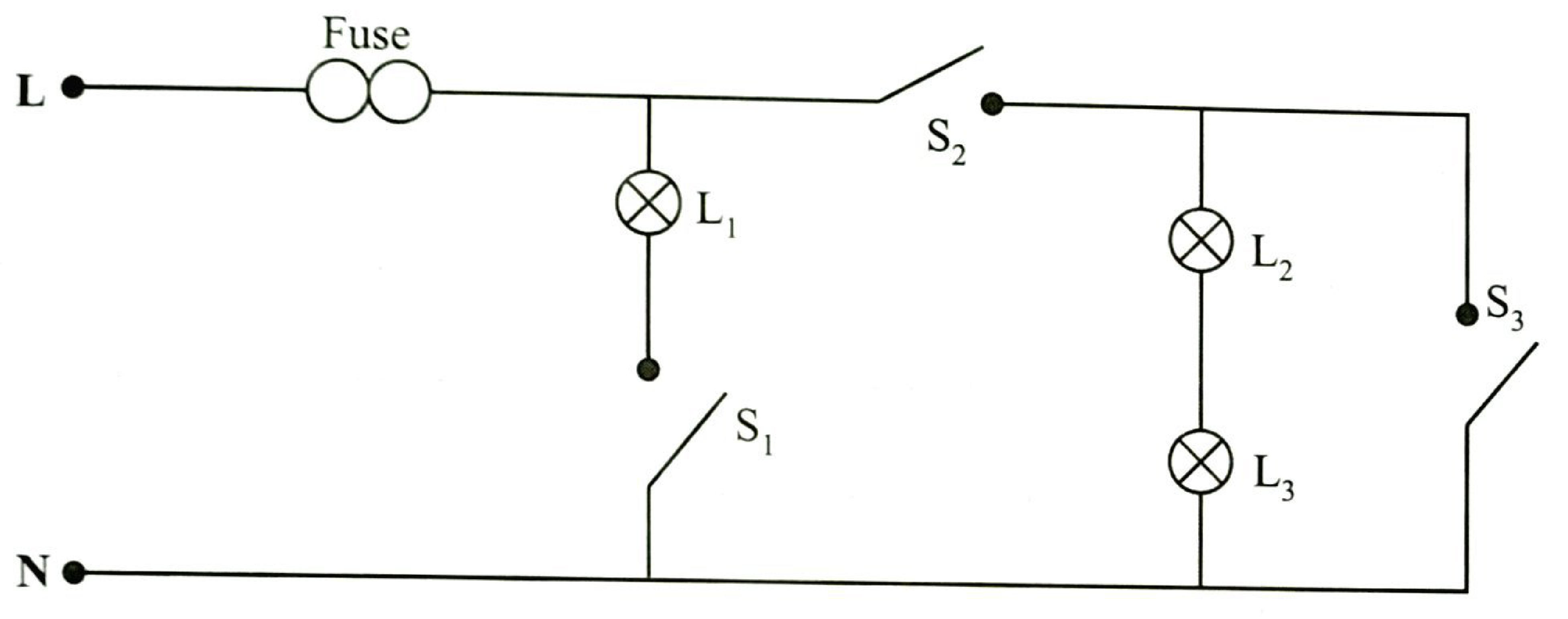
(i) Identify two faults in the circuit. (2 marks)
(ii) State the reasons for the answers in 15(b)(i). (2 marks)
(iii) Describe how the brightness of lamps L₁, L₂ and L₃ compare when switches S₁ and S₂ are closed. (2 marks)
(iv) Explain the answer in 15(b)(iii). (2 marks)
16. (a) Figure 7 shows a circuit consisting of a cell in series with a galvanometer and two metal plates A and B.
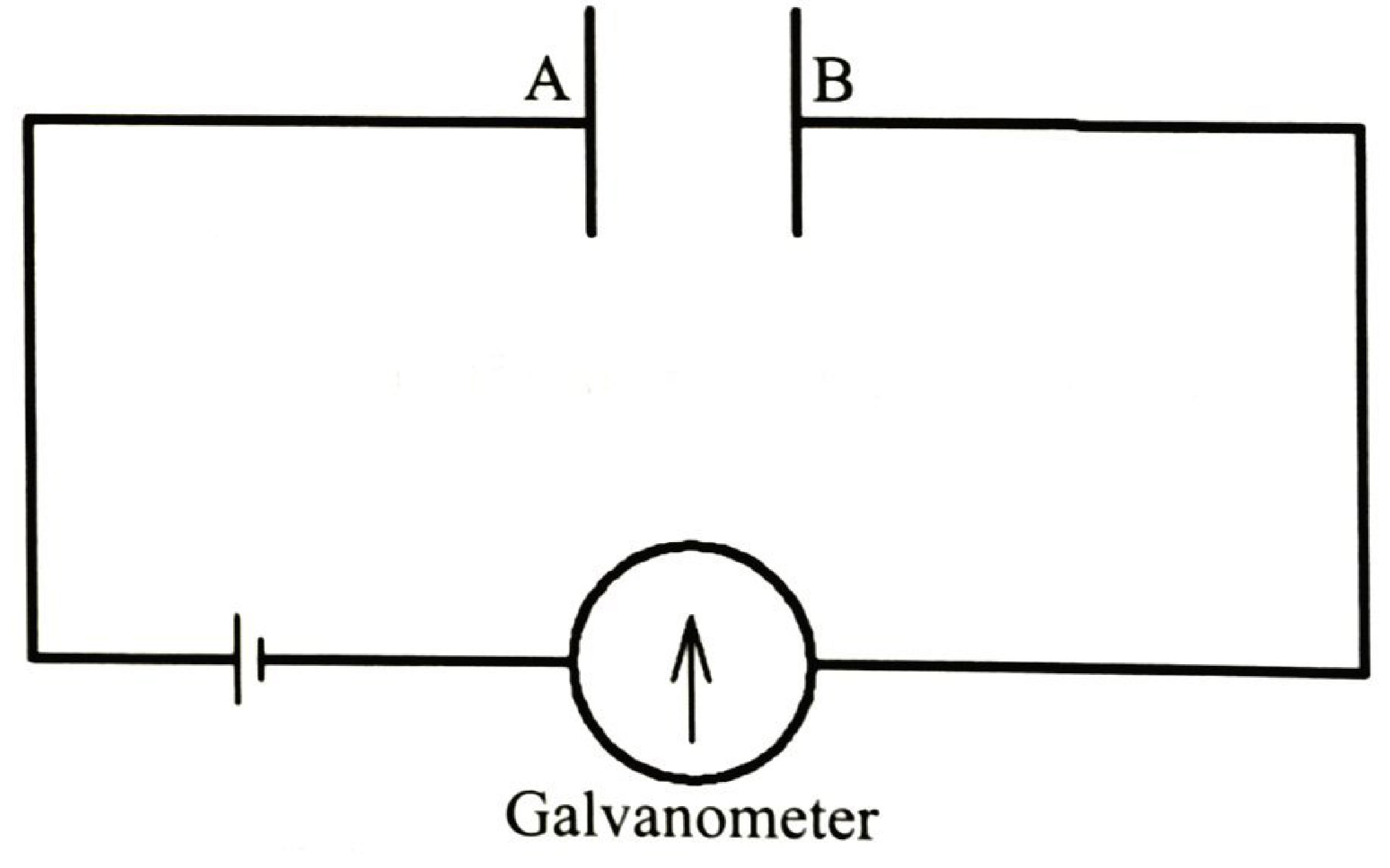
(i) It is observed that when a beam of UV radiation falls on plate B, the galvanometer deflects. Explain this observation. (3 marks)
(ii) Explain what would be observed on the galvanometer when a more intense beam of UV radiation is used. (2 marks)
(b) (i) State with a reason how the intensity of an X-ray beam can be increased in an X-ray tube. (2 marks)
(ii) Figure 8 shows the trace of an a.c. signal on the screen of a cathode ray oscilloscope (CRO).
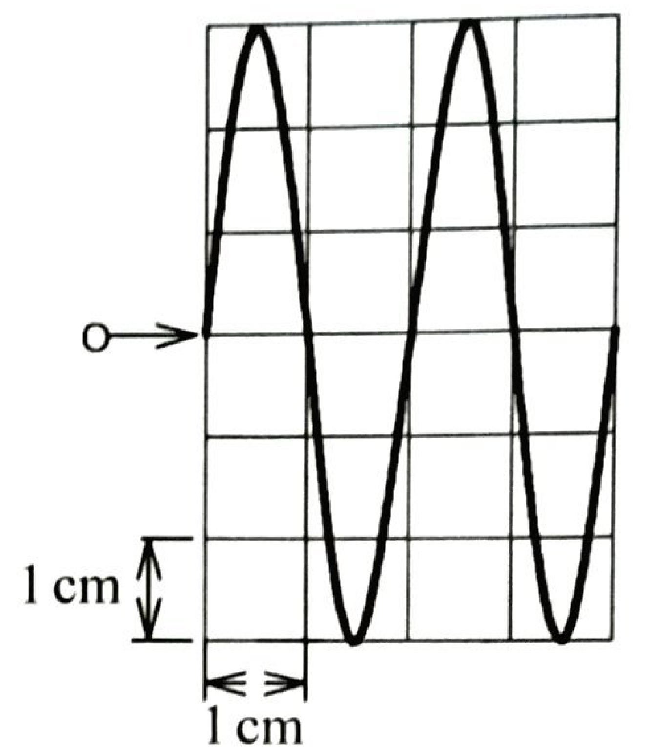
Given that the time-base setting is 8.5 milliseconds per cm, determine the: I. wavelength of the a.c. signal (on the screen); (1 mark) II. frequency of the a.c. signal. (3 marks)
(iii) State the functions of the following parts of a CRO: I. the grid; (1 mark) II. the filament. (1 mark)
17. (a) State one hazard of radioactivity. (1 mark)
(b) Figure 9 shows a decay curve of a radioactive element.
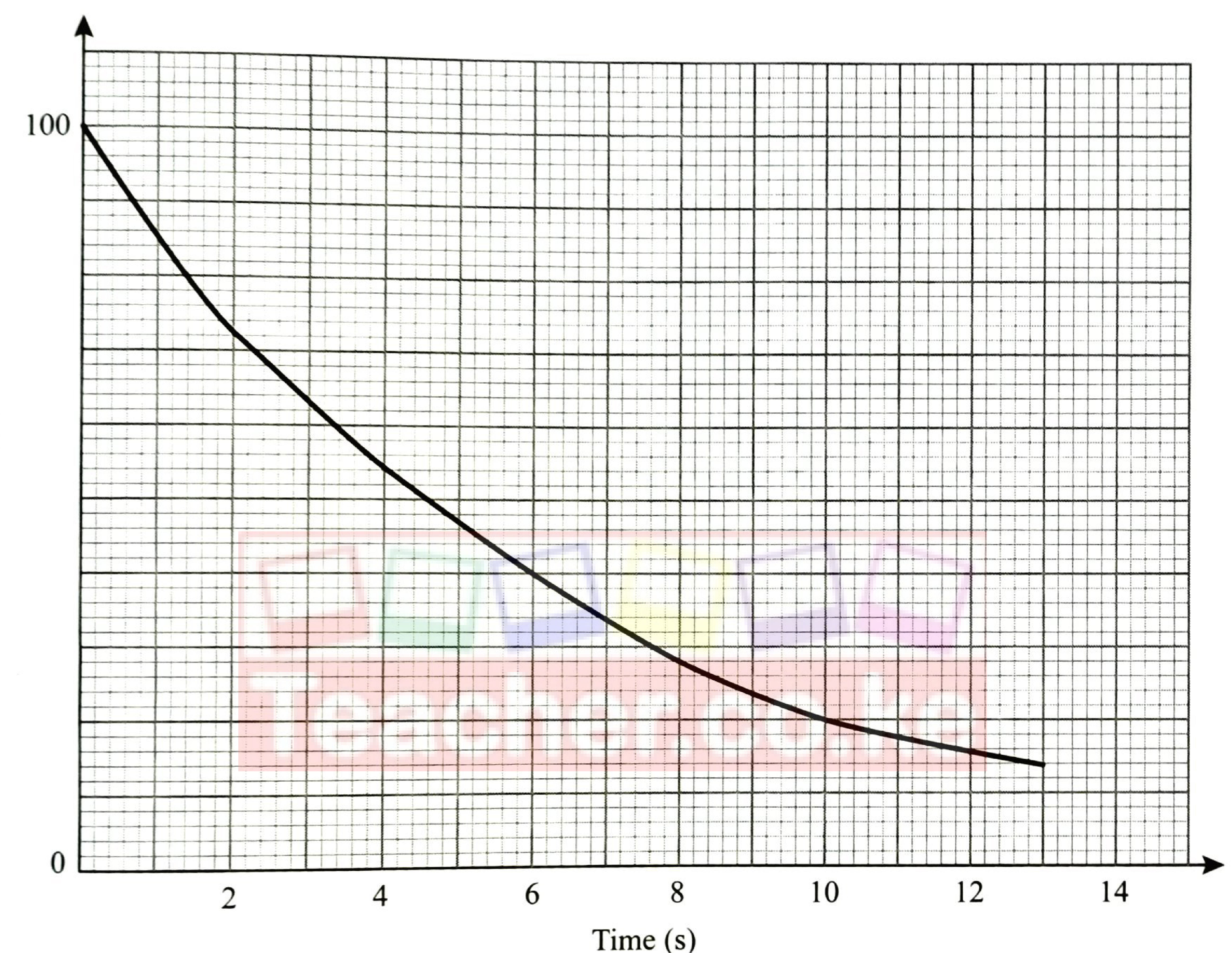
From the graph determine: (i) the half-life of the element; (1 mark) (ii) the number of half-lives it will have undergone when the count is 12.5. (2 marks)
(c) (i) State the effect of doping on a semiconductor. (1 mark)
(ii) Explain how doping produces an n-type semiconductor from a pure semiconductor. (3 marks)
(iii) Figure 10 shows a circuit consisting of two galvanometers G₁ and G₂, two switches S₁ and S₂, a cell and two diodes D₁ and D₂.
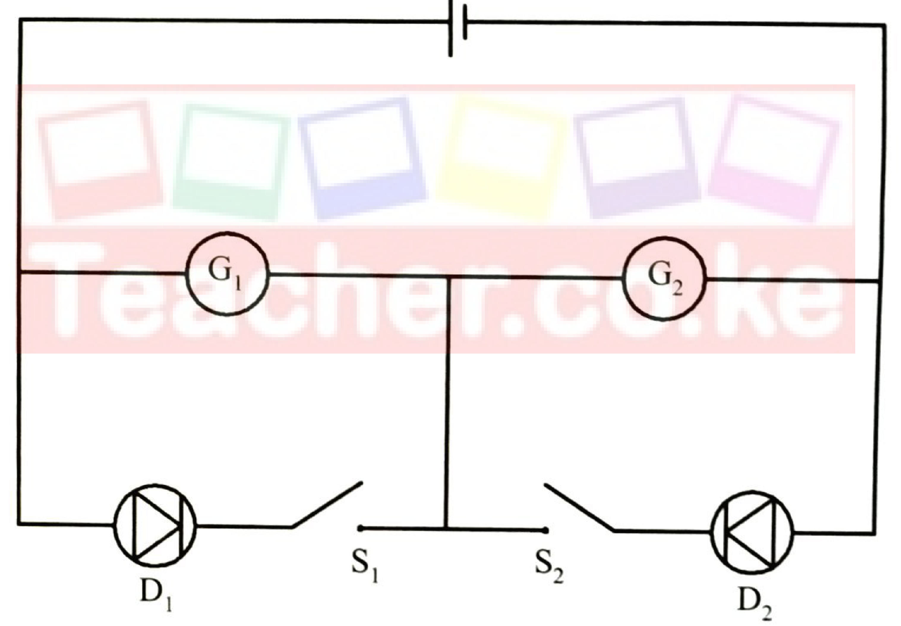
Explain what is observed when S₁ and S₂ are closed. (4 marks)
18. (a) Explain the effect on the resistance of a diode when the forward bias voltage is increased. (2 marks)
(b) Figure 11 shows a circuit consisting of a 12 V battery, a 1.5 kΩ resistor, a light dependent resistor (LDR) and a lamp of negligible resistance. The circuit can be used as a light detector.
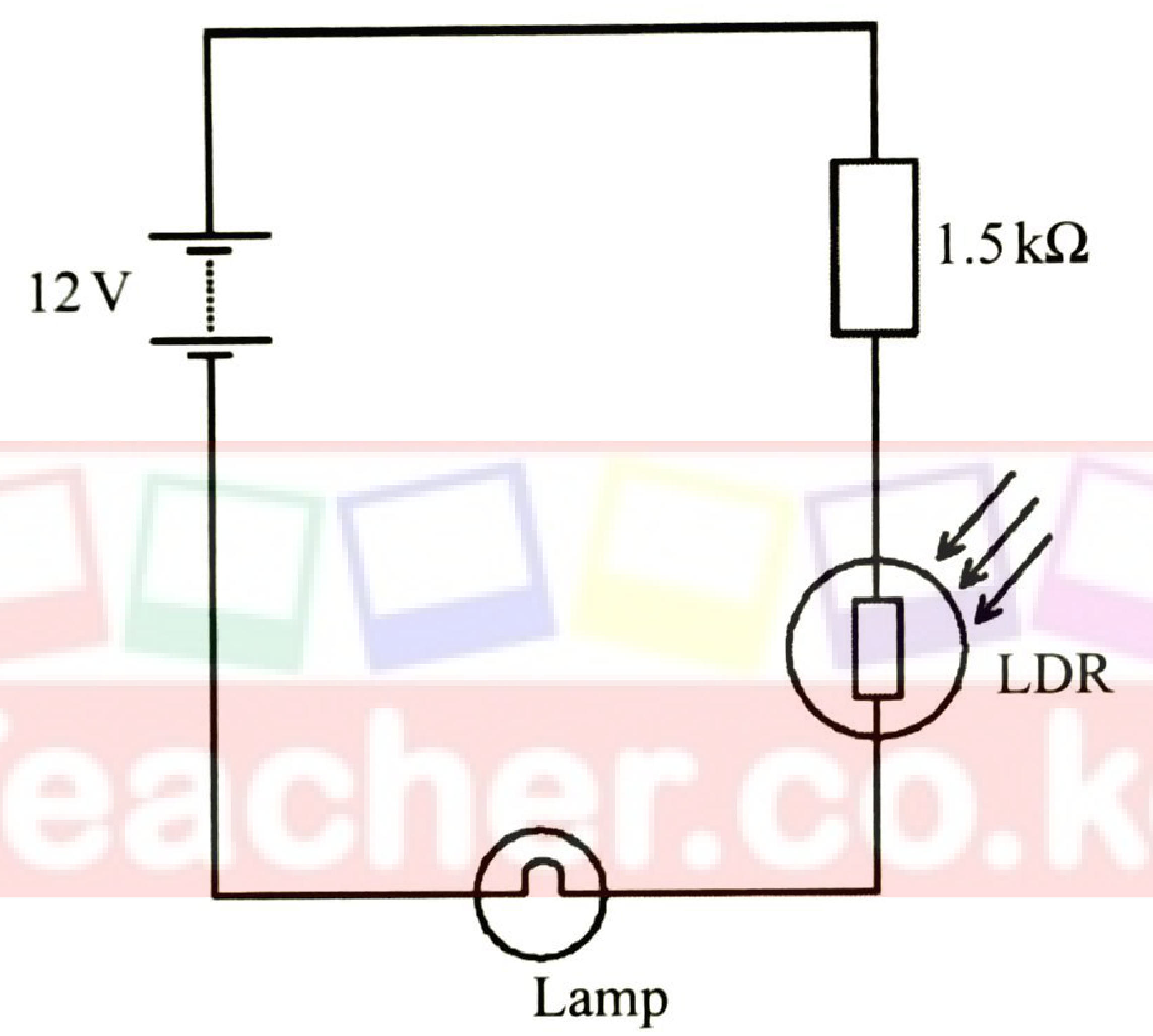
(i) Explain what would be observed if the lighting conditions are changed from total darkness to bright light. (3 marks)
(ii) If the resistance of the LDR in bright light is Ω, determine the potential difference across the 1.5 kΩ resistor. (3 marks)
(c) State the function of a capacitor in rectification of an alternating voltage. (1 mark)
(d) Figure 12 shows two capacitors of 2.5 μF and 10 μF in series with a 12 V battery.
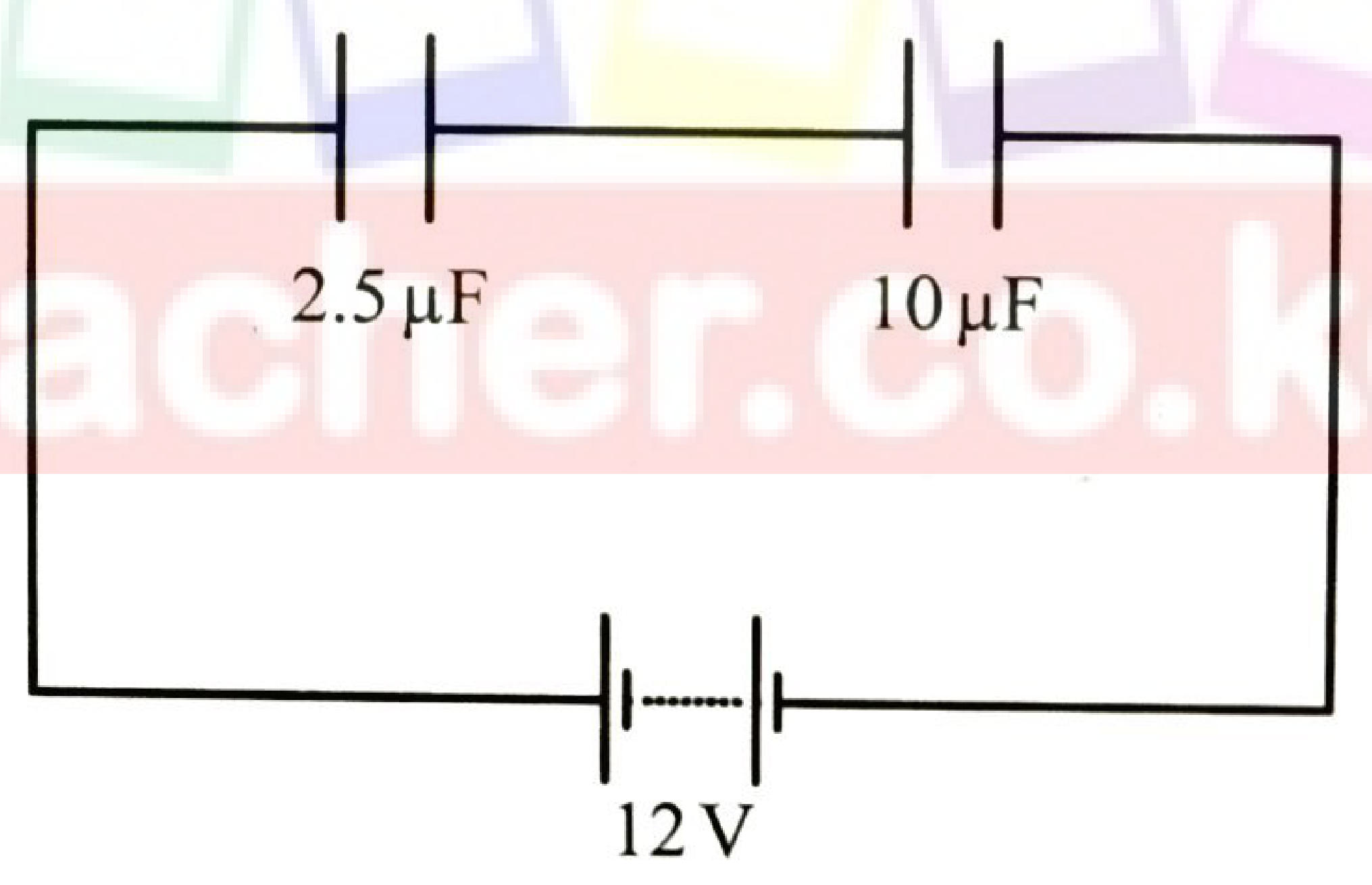
Determine the total charge stored by the capacitors. (3 marks)